Lathe attachment and how to use it (figure)
(1) The working range of the machine tool can be expanded. Due to the variety of workpieces and the limited number and types of machine tools, different fixtures can be used to achieve multi-function and improve the utilization of machine tools.
(2) Stabilizing the quality of the workpiece After the fixture is used, the mutual position of each surface of the workpiece is guaranteed by the fixture, which is higher than the machining accuracy achieved by the alignment correction, and the positioning accuracy and machining accuracy of the same batch of one piece are basically the same. Therefore, the workability of the workpiece is high. (3) Improve productivity and reduce costs. The use of clamps generally simplifies the installation of the workpiece, thereby reducing the amount of auxiliary time required to mount the workpiece. At the same time, the fixture can be used to stabilize the workpiece installation, improve the rigidity of the workpiece processing, increase the cutting amount, reduce the maneuver time and increase the productivity.(4) Improve working conditions. It is convenient, labor-saving and safe to install the workpiece with the clamp, which not only improves the working conditions, but also reduces the technical requirements of the workers.
1. Mount the workpiece with a four-jaw chuckThe shape of the four-jaw chuck is shown in Figure 1a. Its four claws move independently through 4 screws. It is characterized by the ability to clamp non-rotating bodies of complex shapes such as squares, rectangles, etc., and has a large clamping force. Because it can not be self-centering after clamping, the clamping efficiency is low. When staking, the stencil or the dial indicator must be used to align the center of the workpiece with the center of the lathe spindle. Figure 1b shows the dial indicator. Find a schematic diagram of the outer circle.
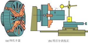
Figure 1 Four-jaw chuck clamping workpiece
2. Install the workpiece with the tip
For shaft-type workpieces with high coaxiality requirements and need to be turned-to-head processing, commonly used double-tip clamping workpieces, as shown in Figure 2, the front tip is a common tip, installed in the spindle hole, and rotates with the spindle, the rear tip The live top is mounted in the tailstock sleeve. The workpiece is centered between the front and rear apex using the center hole and rotates with the spindle through the dial and the clamp.
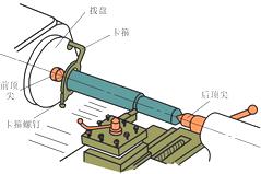
Figure 2 Installing the workpiece with the tip
Pay attention to the installation of the workpiece with the tip:
1) The support screws on the clamps cannot be supported too tightly to prevent deformation of the workpiece.
2) Since the torque is transmitted by the clamp, the cutting amount of the turned workpiece is small.
3) When drilling the center hole at both ends, first use the turning tool to level the end face, and then drill the center hole with the center drill.
When installing the dial and the workpiece, first wipe the internal thread of the dial and the external thread of the spindle end, screw the dial onto the spindle, and then attach one end of the shaft to the clamp. Finally, the workpiece is mounted in the middle of the double tip.
3. Mount the workpiece with the mandrel
When the inner hole is used as the positioning reference, and the coaxiality requirement of the outer circle axis and the inner hole axis can be ensured, the mandrel is positioned at this time, and the workpiece is positioned with a cylindrical hole to locate a common cylindrical mandrel and a small taper mandrel; Workpiece positioning of threaded holes and spline holes, commonly used corresponding cone mandrel, threaded mandrel and spline mandrel.
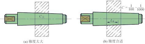
Figure 3 Positioning on a cylindrical mandrel
The cylindrical mandrel is centered on the outer cylindrical surface and the end surface is pressed to clamp the workpiece, as shown in Fig. 3. The mandrel and the workpiece hole are generally matched by the clearance of H7/h6 and H7/g6, so the workpiece can be easily placed on the mandrel. However, due to the large clearance, it is generally only possible to ensure a coaxiality of about 0.02 mm. In order to eliminate the gap and improve the positioning accuracy of the mandrel, the mandrel can be made into a cone, but the taper of the cone is small, otherwise the workpiece will be skewed on the mandrel (see Figure 4a). The commonly used taper is C=1/1000~1/5000. When positioning, the workpiece is wedged on the mandrel, and the hole is elastically deformed after the wedge is closed (Fig. 4b), so that the workpiece is not tilted.
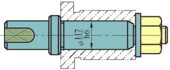
Figure 4 Contact of the cone mandrel mounting workpiece
The advantage of the small taper mandrel is that the friction force generated by the wedge is used to drive the workpiece, and no other clamping device is required, and the centering precision is high, up to 0.005~0.01mm. The disadvantage is that the axial direction of the workpiece cannot be positioned.
When the diameter of the workpiece is not too large, a taper mandrel (taper 1:1000 to 1:2000) can be used. The workpiece is sleeved and pressed against the mandrel by friction. The taper mandrel is accurate in alignment, high in machining accuracy, convenient in loading and unloading, but cannot withstand excessive torque.
When the diameter of the workpiece is large, a cylindrical mandrel with a compression nut should be used. Its clamping force is large, but the centering accuracy is lower than that of the tapered mandrel.
Next page
Plastic Film Washing Machine,Plastic Recycling Machines,Plastic Recycling Machine
Futian Machinery Co., Ltd. , http://www.skywin-extruder.com