Body-in-white projection welding technology
Projection Welding Equipment and Working Principle
Projection welding is a specialized type of spot welding that is widely used in the manufacturing of sheet metal components. The equipment typically consists of a standard spot welding machine equipped with a projection welding head. This setup allows for the precise application of heat and pressure to join two or more metal parts at specific points. Figure 1 shows two common types of projection welders used in industrial applications.
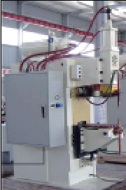
(a) Ordinary Projection Welder
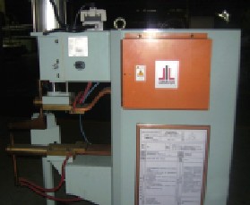
(b) Shaped Projection Welder
Figure 1: Projection Welding Machine
The working principle of projection welding involves placing the sheet metal part on the lower electrode, with a positioning pin passing through the pre-formed hole in the plate. The pin then fits into the threaded hole of the projection nut. As the upper electrode lowers, pressure and current are applied, resulting in localized heating and fusion at the contact point.

Figure 2: Working Principle of Projection Welding
As illustrated in Figure 2, the projection welding process generally involves four main stages: preparation, pressing, energizing, and holding. During the preparation phase, the upper electrode and the workpiece are positioned. In the pressing stage, the projection is compressed under electrode pressure, breaking surface oxides and ensuring good contact. The energizing stage includes the crushing of the bump and the formation of a weld nugget. Finally, during the holding phase, the current is concentrated at the bump location, and it is fully flattened to complete the weld.
Key Points in Projection Welding
Although projection welding is a versatile technique, its application on sheet metal parts has certain limitations. Not all shapes or positions on the plate can be welded using this method. Careful attention must be given to several key factors to ensure high-quality results and avoid unnecessary costs and delays.
1. **Positioning and Design Considerations** - The convex part should be aligned perpendicular to the axis of the projection nut or bolt. The distance from the edge of the part should be greater than the throat depth of the welder (typically 420–770 mm) to prevent interference. - For special designs, consider using custom electrodes, though this may increase costs and reduce quality. - Long strip-shaped parts should have a length ≤ 1500 mm for ease of handling. - Square stamping parts should have side lengths ≤ 1000 mm for worker convenience. - The weight of stamping parts should not exceed 7.5 kg to reduce labor intensity. - Avoid using M5 or smaller nuts due to weak weld strength, difficulty in procurement, and higher costs. - Use the same size and specification (e.g., M6) for projection nuts on the same part. - Try to weld projection nuts on both sides of the part to minimize extra workload.
2. **Clearance and Safety** - Maintain a minimum clearance of 3 mm between the projection tip and the workpiece. This includes 1.5 mm for stamping tolerance, 0.5 mm for projection welding tolerance, and 1 mm as a safety margin. - It is recommended to re-arc weld after projecting M10 and above to ensure proper fusion.
3. **Material Thickness Matching** - To ensure consistent weld quality, match the projection nut or bolt thickness with the sheet metal thickness. Table 1 provides a reference for this correspondence.
Table 1: Correspondence Between Projection Nut (Bolt) and Sheet Thickness

4. **Avoidance of Interference** - When both projection welding and stud welding are used on the same part, ensure that the center of the stud is at least 15 mm away from the edge of the projection weld. This prevents interference and ensures accurate welding.

Figure 3: Stud Welding Avoidance of Projection Welding
Quality Inspection of Projection Welding
The inspection of projection welding typically includes two main aspects: installation performance and welding strength. Installation performance is usually checked visually. If visual inspection is inconclusive, matching bolts or nuts can be tested on-site to verify fit and function. Welding strength is measured using a torque wrench to ensure it meets the required specifications (see Table 2). If the specified torque is not achieved, the welding parameters must be adjusted until the test passes.
Table 2: Comparison of Welding Specifications and Test Torque

Conclusion
Projection welding has been a fundamental process in body-in-white manufacturing for many years, and the technology is well-established. However, with the increasing use of galvanized and high-strength steel sheets in recent years, the focus on optimizing the process and improving weld quality has grown significantly. As one of the four major welding methods in automotive manufacturing—alongside spot welding, arc welding, and stud welding—projection welding plays a critical role in assembling over 90% of vehicle bodies. Therefore, maintaining high-quality standards in projection welding is essential for the overall performance and longevity of the vehicle. With continuous advancements in materials and vehicle design, the importance of reliable projection welding will only continue to rise.
Storage Holders & Racks,Indoor Storage Racks,Shelf Furniture Storage Racks,Storage Racks
Changzhou Offistyle Furniture Co., Ltd. , https://www.offistylefurniture.com